555 Timer Schematic : 555 Timer Ic Working Principle Block Diagram Circuit Schematics - 555 timer helpers schematic adding of a resistor and capacitor to the trigger will not work for very short trigger or output pulses because there is a rc delay in the decay and recovery of the voltage at the trigger.
555 Timer Schematic : 555 Timer Ic Working Principle Block Diagram Circuit Schematics - 555 timer helpers schematic adding of a resistor and capacitor to the trigger will not work for very short trigger or output pulses because there is a rc delay in the decay and recovery of the voltage at the trigger.. In other words, 555 timer is a circuit which may be connected as a stable or monostable multivibrator. The 555 timer ic is an integrated circuit (chip) used in a variety of timer, delay, pulse generation, and oscillator applications. Between the positive supply voltage v cc and the ground gnd is a voltage divider consisting of three identical resistors, which create two reference voltages at 1 ⁄ 3 v cc and 2. Astable mode, monostable mode and bistable mode are the three modes of operation of ic 555. The internal block diagram and schematic of the 555 timer are highlighted with the same color across all three drawings to clarify how the chip is implemented:
In the previous tutorials of the 555 timer project series, we have learnt how the trigger pin (pin2) and the threshold pin (pin6) of the 555 timer ic sense voltages and control the output. Astable mode, monostable mode and bistable mode are the three modes of operation of ic 555. In other words, 555 timer is a circuit which may be connected as a stable or monostable multivibrator. In 2017, it was said over a billion 555 timers are pr. I have used two 555 timer ics in this project and both these 555 ics act as astable multivibrators.
Extended Period 555 On Pulse Timer from www.electroschematics.com The internal block diagram and schematic of the 555 timer are highlighted with the same color across all three drawings to clarify how the chip is implemented: We need to set 555 timer in monostable mode to build timer. Dec 07, 2018 · 555 timer ic. I have used two 555 timer ics in this project and both these 555 ics act as astable multivibrators. Jul 14, 2015 · we can use this property of 555 timer to create various timer circuits like 1 minute timer circuit, 5 minute timer circuit, 10 minute timer circuit, 15 minute timer circuit, etc. Oct 13, 2018 · the 555 timer ic is an integrated circuit used in a variety of timer, pulse generation and oscillator applications. It only turns on at a pulse and then shuts off after the pulse has passed. The 555 timer ic is an integrated circuit (chip) used in a variety of timer, delay, pulse generation, and oscillator applications.
Ic 555 timer ic is one of the most popular integrated circuit chip used for a variety of applications such as astable, monostable, bistable multivibrators, timer circuits, oscillators, pwm (pulse width modulation), ppm (pulse position modulation), square wave generator or pulse generator, etc.
Astable mode, monostable mode and bistable mode are the three modes of operation of ic 555. Working and schematic diagram of clap swith circuit Dec 07, 2018 · 555 timer ic. Oct 13, 2018 · the 555 timer ic is an integrated circuit used in a variety of timer, pulse generation and oscillator applications. For a stable operation as an oscillator , the We need to set 555 timer in monostable mode to build timer. The internal block diagram and schematic of the 555 timer are highlighted with the same color across all three drawings to clarify how the chip is implemented: Between the positive supply voltage v cc and the ground gnd is a voltage divider consisting of three identical resistors, which create two reference voltages at 1 ⁄ 3 v cc and 2. I have used two 555 timer ics in this project and both these 555 ics act as astable multivibrators. In more simple words, 555 timer is a monolithic timing circuit, which can produce accurate timing pulses with 50% or 100% duty cycle. When a 555 timer creates pulses in this way, the led doesn't stay constantly on. In monostable mode, the duration for. In other words, 555 timer is a circuit which may be connected as a stable or monostable multivibrator.
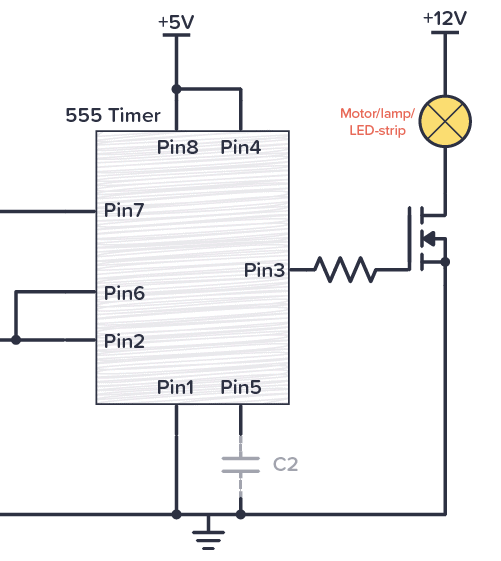
Oct 13, 2018 · the 555 timer ic is an integrated circuit used in a variety of timer, pulse generation and oscillator applications. In the previous tutorials of the 555 timer project series, we have learnt how the trigger pin (pin2) and the threshold pin (pin6) of the 555 timer ic sense voltages and control the output. It was commercialized in 1972 by signetics. When a 555 timer creates pulses in this way, the led doesn't stay constantly on. I have used two 555 timer ics in this project and both these 555 ics act as astable multivibrators.
555 Timer from sound-au.com In more simple words, 555 timer is a monolithic timing circuit, which can produce accurate timing pulses with 50% or 100% duty cycle. In other words, 555 timer is a circuit which may be connected as a stable or monostable multivibrator. It only turns on at a pulse and then shuts off after the pulse has passed. Working and schematic diagram of clap swith circuit Jul 14, 2015 · we can use this property of 555 timer to create various timer circuits like 1 minute timer circuit, 5 minute timer circuit, 10 minute timer circuit, 15 minute timer circuit, etc. Derivatives provide two (556) or four (558) timing circuits in one package. The internal block diagram and schematic of the 555 timer are highlighted with the same color across all three drawings to clarify how the chip is implemented: Ic 555 timer ic is one of the most popular integrated circuit chip used for a variety of applications such as astable, monostable, bistable multivibrators, timer circuits, oscillators, pwm (pulse width modulation), ppm (pulse position modulation), square wave generator or pulse generator, etc.
I have used two 555 timer ics in this project and both these 555 ics act as astable multivibrators.
Ic 555 timer ic is one of the most popular integrated circuit chip used for a variety of applications such as astable, monostable, bistable multivibrators, timer circuits, oscillators, pwm (pulse width modulation), ppm (pulse position modulation), square wave generator or pulse generator, etc. In other words, 555 timer is a circuit which may be connected as a stable or monostable multivibrator. For a stable operation as an oscillator , the Jul 14, 2015 · we can use this property of 555 timer to create various timer circuits like 1 minute timer circuit, 5 minute timer circuit, 10 minute timer circuit, 15 minute timer circuit, etc. Dec 07, 2018 · 555 timer ic. I have used two 555 timer ics in this project and both these 555 ics act as astable multivibrators. We need to set 555 timer in monostable mode to build timer. Derivatives provide two (556) or four (558) timing circuits in one package. In monostable mode, the duration for. The 555 timer ic is an integrated circuit (chip) used in a variety of timer, delay, pulse generation, and oscillator applications. 555 timer helpers schematic adding of a resistor and capacitor to the trigger will not work for very short trigger or output pulses because there is a rc delay in the decay and recovery of the voltage at the trigger. In the time delay mode of operation, the time is precisely controlled by one external resistor and capacitor. 555 timer is a digital monolithic integrated circuit (ic) which may be used as a clock generator.
In the previous tutorials of the 555 timer project series, we have learnt how the trigger pin (pin2) and the threshold pin (pin6) of the 555 timer ic sense voltages and control the output. Ic 555 timer ic is one of the most popular integrated circuit chip used for a variety of applications such as astable, monostable, bistable multivibrators, timer circuits, oscillators, pwm (pulse width modulation), ppm (pulse position modulation), square wave generator or pulse generator, etc. All we need to change the value of resistor r1 and/or capacitor c1. Dec 07, 2018 · 555 timer ic. It only turns on at a pulse and then shuts off after the pulse has passed.
555 Timer Tutorial And Circuits Build Electronic Circuits from www.build-electronic-circuits.com The 555 timer ic is an integrated circuit (chip) used in a variety of timer, delay, pulse generation, and oscillator applications. When a 555 timer creates pulses in this way, the led doesn't stay constantly on. Jul 14, 2015 · we can use this property of 555 timer to create various timer circuits like 1 minute timer circuit, 5 minute timer circuit, 10 minute timer circuit, 15 minute timer circuit, etc. 555 timer is a digital monolithic integrated circuit (ic) which may be used as a clock generator. In monostable mode, the duration for. It was commercialized in 1972 by signetics. Between the positive supply voltage v cc and the ground gnd is a voltage divider consisting of three identical resistors, which create two reference voltages at 1 ⁄ 3 v cc and 2. Working and schematic diagram of clap swith circuit
555 timer is a digital monolithic integrated circuit (ic) which may be used as a clock generator.
The internal block diagram and schematic of the 555 timer are highlighted with the same color across all three drawings to clarify how the chip is implemented: Oct 13, 2018 · the 555 timer ic is an integrated circuit used in a variety of timer, pulse generation and oscillator applications. Dec 07, 2018 · 555 timer ic. Jul 14, 2015 · we can use this property of 555 timer to create various timer circuits like 1 minute timer circuit, 5 minute timer circuit, 10 minute timer circuit, 15 minute timer circuit, etc. In more simple words, 555 timer is a monolithic timing circuit, which can produce accurate timing pulses with 50% or 100% duty cycle. All we need to change the value of resistor r1 and/or capacitor c1. It only turns on at a pulse and then shuts off after the pulse has passed. Working and schematic diagram of clap swith circuit For a stable operation as an oscillator , the It was commercialized in 1972 by signetics. Between the positive supply voltage v cc and the ground gnd is a voltage divider consisting of three identical resistors, which create two reference voltages at 1 ⁄ 3 v cc and 2. When a 555 timer creates pulses in this way, the led doesn't stay constantly on. In other words, 555 timer is a circuit which may be connected as a stable or monostable multivibrator.


Komentar
Posting Komentar